Boards Screen

This screen displays a view of the boards in the current circuit and allows them to be edited.
Circuit Description
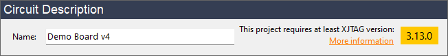
Enter a descriptive name for the circuit in the "Name" field. This field is also used for generation of log files when running code in XJDeveloper or XJRunner.
The minimum XJTAG version required to open the current project is displayed in the top right. Click the More information link to open the Project Compatibility Report dialog that shows the reasons for this minimum version.
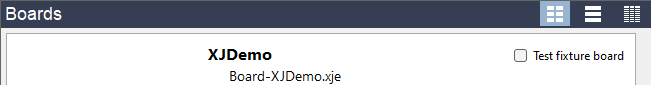
Boards
The boards screen has 3 different display modes that are selected using the buttons at the top right of the Boards panel.
 Tile Mode - arranges boards horizontally as interactive tiles
 Row Mode - arranges boards vertically as interactive rows. This is the default mode.
 Grid Mode - arranges all board data in a grid. Similar to the display used in older versions of XJTAG.
To add a board to your project click the  Add New... button on the toolbar at the bottom of the boards panel to launch the Add Board Dialog. In Tile or Row mode this can alternatively be done by clicking on the Add New Board... tile or row.
If you have already created a board in another project and want to reuse it, click  Import Existing... on the toolbar at the bottom of the boards panel. This will open the Import Existing Board Dialog.
If you do not have the netlist for a board that you want to add to the project, click the  Create without netlist... button on the toolbar at the bottom of the boards panel to launch the Manually Create Board Wizard.
After adding a manually created board to the project, the  Learn Connections... button will also appear on the toolbar, allowing you to re-run the Learn Connections tool.
After adding boards the screen will show the following information for each board:
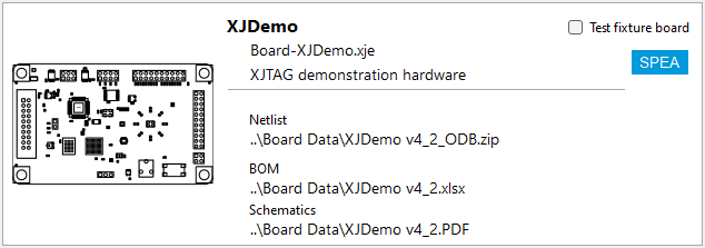
Boards without an ODB++ netlist will show a default icon showing the chosen netlist format. All boards have a Test fixture board checkbox that can be ticked to indicate the board is not the UUT but a board connected to extend test coverage. It is possible to reduce the fault information output by the connection test for boards marked as test fixture board by changing the "Reduce output for test fixture boards" setting in the Connection Test Settings.
To edit a board, double-click it or select the board and click the  Edit... button on the toolbar at the bottom of the boards panel.
To remove a board from the circuit, select the board and click
the  Remove button on the toolbar.
BOM Information
To edit the BOM information of a board, select the board and click the  BOM Settings... drop-down menu and select which BOM source (netlist, file or schematic) to configure. An Import BOM dialog is launched for that source and board. This can alternatively be done for any source when editing the board.
To export the combined BOM information from all the different BOM sources to a CSV file, select Export BOM... from the BOM Settings... menu.
Assigning PDF Files to a Boards Schematic
To add or edit the PDF files associated with your boards schematic; select the board and click  Schematic Files... to launch the Assign Schematic Files Dialog. Any suitable BOM information in the schematic can also be imported through the dialog. This can alternatively be done when editing the board or by clicking the schematic path in Tile or Row Mode.
Displaying the Layout Viewer
To display the Layout Viewer from the Boards Screen, select a board with an ODB++ netlist and click View then  Layout Viewer at the bottom of the boards panel. This will launch the Layout Viewer for that board.
Displaying the Schematic Viewer
To display the Schematic Viewer from the Boards Screen, select a board with a PDF file (or files) and click View then Schematic at the bottom of the boards panel. This will launch the Schematic Viewer for that board.
Adding External Hardware Information
To add or edit the external hardware associated with a board, click the  External Hardware drop-down menu and select Add... to add external hardware information to the board, or Edit... to edit the existing external hardware information on the board. These options open the Edit ICT Information Dialog. This can alternatively be done when editing the board.
Selecting Rules for Unfitted Device Suggestion
To select which rules XJDeveloper uses for suggesting unfitted devices, click on the  Unfitted Rules... button to launch the Unfitted Suggestion Rules Dialog.
XJTAG v4.3.0