A Guide to JTAG Pin-out
Although JTAG does not define where the signals are positioned on a connector, many JTAG systems such as emulators and debuggers have fixed, pre-defined pin-outs. In contrast, XJTAG controllers have a configurable pin-out, so if you have the freedom to allocate the JTAG pin assignments, it is strongly recommended they be set using the following guidelines:
- Ensure each TAP has its own dedicated ground (as described here).
- Keep TDO away from TCK, preferably separating them in the cable with a ground wire to reduce the chance of crosstalk from TDO inducing glitches on TCK.
- Run TCK adjacent to a ground wire.
- Ideally, interleave all signals in the cable with ground connections. If you are using an XJLink2, although it only has 2 Hard GND pins, it has soft ground pins which can be used for this purpose. If a standard 2-row ribbon-cable connector is being used, this can be done on by defining all even-numbered pins as ground. This would also allow the use of twisted-pairs should performance need to be improved further.
The following pin-out is a suitable arrangement when two TAPs are being used and the cable therefore needs to split to go to two connectors:
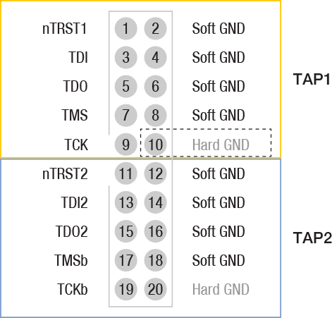
Figure 3: Recommended pin-out when 2 TAPS share a connector
If you are using an XJLink2, spare even-numbered pins (for example if only a single TAP is used), should be utilised to connect multiple grounds to the board under test. If you are using an XJLink-PF series controller, there are 10 GND pins per connector available for you to use to help ensure signal integrity.
- A board with multiple JTAG devices may have just one JTAG header with the ICs cascaded in a single chain, or it might contain multiple JTAG chains and consequently several headers. There are various reasons why more than one chain might be used, including the way some manufacturers’ own tools do not work well with other devices in the chain, or to allow the parts to run in different voltage domains.
- Some chains might consist of a single JTAG device while others may contain multiple devices from one manufacturer, but all combinations are supported for boundary scan testing, and XJTAG can run all the chains simultaneously for maximum test coverage.
- Different form factors of XJLink2 (e.g. PXI-XJLink2, XJLink2-3030) have different connectors. However, they all have the same capabilities, and a project can therefore be moved to different types of XJLink2 without having to change the pin-out definition. More thought may be required when transferring a project that uses the XJLink2 family to an XJLink of a different family (e.g. XJLink-PF series.)
XJTAG v4.3.0