Test Coverage
Test coverage is one of the most important factors to consider when designing the test strategy for your circuit. Whether you plan to use XJDeveloper alone or as part of a hybrid test solution, the  Test Coverage screen in XJDeveloper can provide valuable information.
This exercise is based on the XJDemo v4 board. Completing the XJDeveloper Tutorial before you work through this exercise will provide very useful background knowledge of this board and the structure of its XJTAG project.
The starting project for this exercise is installed as a zip file: CompletedTutorial4.zip, as part of the XJTAG installation.
- Extract the zip file CompletedTutorial4.zip to a directory of your choice.
- Navigate to the Board Test directory.
- Open XJDemo Board.xjd using XJDeveloper.
- Click the Test Coverage screen button under the Setup header.
- Click on the Chart View tab.
This test coverage is derived from three sources:
- The Connection Test that XJTAG automatically runs using the description of the circuit defined in the project.
- Tests in Test Device Files that interact with the functionality of the devices on the board that do not have JTAG capability. These tests are not designed to test the functionality of these devices; they are designed to add test coverage by proving that the devices are correctly connected to the board.
- Functional Tests that are defined on the Test Coverage screen. Functional Tests allow you to tell the system about coverage that is achieved by running tests that do not fall into either of the categories above.
Connection Test
XJDeveloper will automatically calculate the test coverage that will be achieved by running the Connection Test. The coverage is split into four types:
- Opens - This coverage is achieved in two ways. The most direct method drives a signal from one pin and makes sure the expected digital values are read by other pins on the same net. A less direct method uses pull resistors: nets are driven against a pull resistor and then tri-stated to check that the expected pull value is read back. This test checks for open-circuit faults at both the driving pin and the pin on the pull resistor.
-
Shorts - This coverage is achieved by driving patterns of test values on nets while the rest of the nets in the circuit are left tri-state. If the pattern driven is seen on any of the tri-stated nets then a short circuit fault is reported.
This method allows the XJTAG Connection Test to find the highest possible number of short-circuit faults. Many traditional connection tests rely on contention to find short-circuit faults, but this can miss faults where there is resistance between the JTAG pin and the short circuit. The voltage drop across a series resistance can allow one pin to drive high and read high while the other pin can drive low and read low. By driving a test pattern across several test steps while other nets are tri-state, the Connection Test can find this type of short-circuit fault.
- Stuck High and Stuck Low - This coverage is achieved by driving pins high and low and then making sure that those pins read high and low. This test requires that a pin that can both write and read at the same time, or that there is more than one accessible on a net.
Most of the coverage in the Connection Test comes from directly controlling and monitoring JTAG pins. However the Connection Test can also add coverage in all of the categories above by accessing nets via Logic Devices such as buffers and simple logic gates, using PIO pins on the XJLink and in using integration with various ICT machines.
Test Device Files
Unlike the test coverage that comes from Connection Test, XJDeveloper cannot automatically calculate the test coverage achieved by running tests on devices that do not have JTAG capability. In order for this coverage to be reported, the Test Device Files that contain these test functions must declare which busses will be tested and the categories of fault for which they will be tested.
The Test Device Files in the XJEase Library already have test coverage values declared correctly. You will need to configure these settings in any Test Device Files that you create so that the coverage added by running the tests that you write will be correctly reported.
In order to understand what test coverage can reasonably be given to a bus, you will now look at the XJEase library file for the SRAM on the XJDemo board.
- Click the
 Test Device Files screen button under the Setup header.
 - Double-click SRAM 48Pin BGA 4Mb x16.xje in the list of Test Device Files.
When viewing a Test Device File the screen is split into two sections. At the top of the screen there is a text editor where test code is written. At the bottom of the screen there is a set of tabs that are used to setup the non-code elements of the file. The Busses tab is selected by default and it is on this tab that test coverage information is configured.
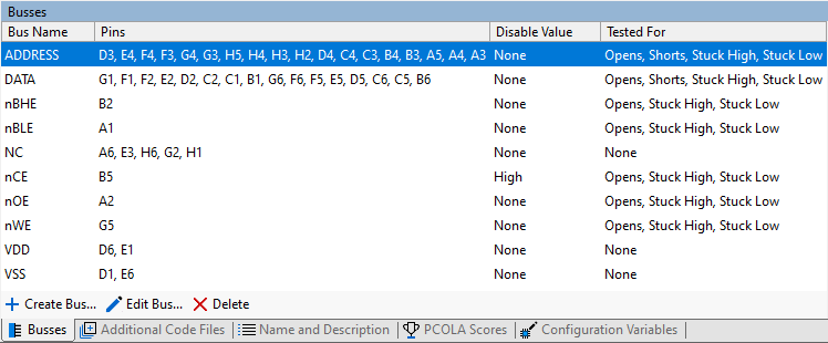
For each bus you can define Tested For values. This coverage will be added to all the other available coverage that is displayed on the Test Coverage screen.
It is important to understand why different busses have to be configured as having different types of coverage.
Opens
Tested for Opens means that you are testing the pins in a bus for open-circuit faults. In order to do this your test must either confirm that a signal is getting into the device from the writeable pin on the net or out of the device into a readable pin on the net.
On the SRAM the ADDRESS bus and the control busses, nOE, nCE, nWE, nBLE and nBHE are input only signals. The way that the test proves that there are no open circuit faults on these busses is to cause the device to output different values on the DATA bus depending on the values of each of these signals.
The DATA bus can be either an input or an output on the SRAM depending on the state of the control signals. Both of these functions are used, firstly to get known data into the device and then to read that data back. The connection of the pins on this bus is confirmed by reading the expected values.
Shorts
Tested for Shorts means that the test verifies that pins in the bus are not shorted to one another. This is a subtly different meaning to the testing for Shorts that is reported by the Connection Test as the Connection Test looks for short circuit faults between all pins that are accessible through the test system.
The ability of the Connection Test to do a comprehensive test for short circuit faults means that it is often not necessary to add this functionality to Test Device File tests.
In the case of the SRAM file the ADDRESS bus and DATA bus have Shorts coverage as the test code has been designed to write carefully selected data values into addresses in such a way as to identify shorts between any of the bits of these busses.
Normally, Test Device Files will not add Shorts coverage to busses.
Stuck High / Stuck Low
Tested for Stuck High or Stuck Low is very similar to testing for open circuit faults in situations when both types of faults can be tested for. This is the case for all of the busses in the SRAM file.
There are cases where it is not possible to test for both Stuck High and Stuck Low faults. One example would be the enable bus on a power regulator where that supply is required in order to keep a JTAG device powered. As the enable pin must be kept at a constant value, it is correct to specify that the bus is tested for not being stuck at the value which would disable the supply, but it is not correct to specify that the bus is not stuck at the value which keeps the device enabled because the opposite value is never used during testing.
In this case it is also not correct to say that the bus is tested for Opens, because the pin may be open-circuit but naturally float to the value required to keep the supply enabled.
Functional
Tested for Functional is used in cases where XJTAG has no direct access, but the functionality of the pins in the bus is tested. One good example where Functional testing should be added to a bus is a serial transceiver, such as RS232. The test in this case requires an external loopback to be attached between the TxOUT (transmit out) signal and the RxIN (receive input) signals. These signals are not accessible from boundary scan but they must be correctly connected and functioning as expected in order for the test to pass.
Functional Tests
Test Device Files are the main way to tell XJDeveloper about test coverage that needs to be added to the levels automatically calculated based on the Connection Test.
There are two reasons why you may want to tell XJDeveloper about additional coverage that cannot be added to Test Device Files:
- You are doing some testing as part of your XJTAG test system that does not easily fit with being added to a Test Device File. This could be testing a cluster of components together, or doing some testing on a particular device that cannot be included in the Test Device File as it cannot be used on every instance of the device type in a circuit.
- You want to use XJDeveloper to aggregate test coverage from test mechanisms other than boundary scan. There may be some section of your board that is not suitable for testing using boundary scan but you have an alternative test methodology. XJDeveloper allows you to describe which components are tested by these other tests so that it can report the overall coverage.
Test coverage display options
On the test coverage screen, there is a checkbox to Only display coverage from enabled tests:
- When ticked, only coverage from those tests that are enabled in the XJRunner Tests list is included. This mode makes it easy to see the coverage contribution from specific test functions. It also allows the coverage increase to be seen as new tests are added to the test list.
- Leaving this unticked is particularly useful for viewing coverage while setting up a project, as the test list may not be complete during the early stages.
The difference between the two modes can help highlight test devices where coverage is assigned but suitable tests are missing from, or not enabled in the test list.
When test functions are automatically added to the test list as you categorise devices, they are enabled by default. This means that changing the display option will not currently have any effect on the reported coverage.
When you create new Test Device Files you can select options to create a template test function and for that function to be added to the test list; however it will be enabled to run by default. Adding new tests, or selecting which tests are enabled is done on the XJRunner Setup screen.
- In the Options pane of the Test Coverage screen, make sure the Only display coverage from enabled tests checkbox in the Coverage Options section is ticked.
- Click the
 XJRunner Setup screen button under the Run and Deploy header.
 - Click the
 None button at the bottom of the test list to clear the selection.
 - Click on the cross next to the CONNTEST test in the XJRunner Tests list to enable the Connection Test.
- Click the Test Coverage screen button under the Setup header.
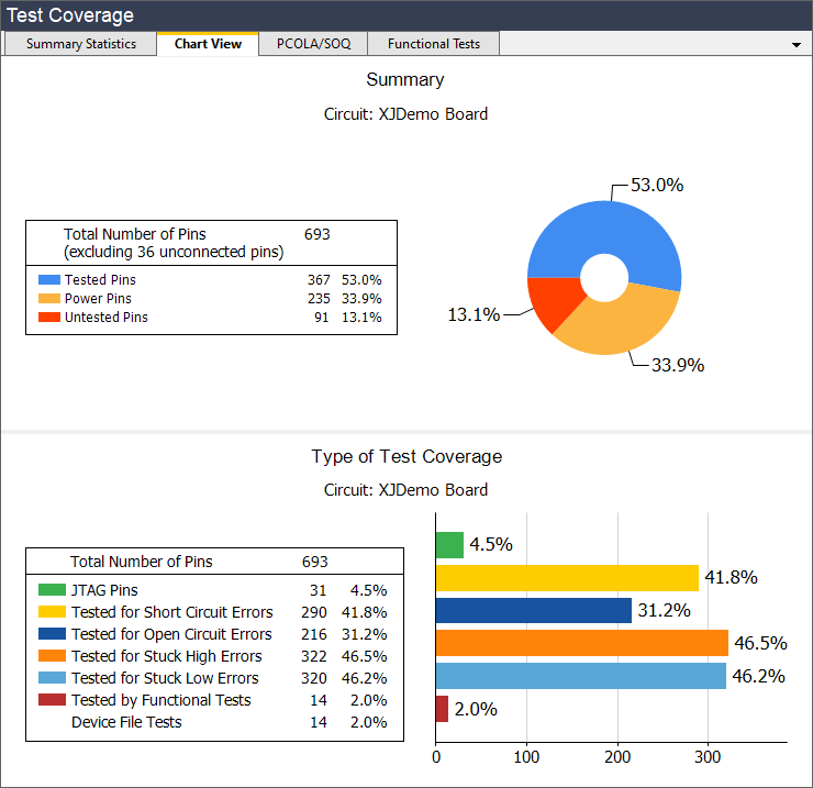
- Click on the Chart View tab to view a summary of the coverage.
The test coverage Summary Statistics and Chart View tabs now only display test coverage from the Connection Test.
- Use the Only display coverage from enabled tests option to toggle between showing coverage from the Connection Test and from all available tests.
The test coverage summary shows that 46.9% of the pins are tested (to some degree) by the Connection Test. This increases to 53.0% for all tests. However, coverage for open-circuit faults increases much more significantly. When examining just the Connection Test, just 73 pins (10.5%) had open circuit coverage; by adding all the rest of the test coverage this increases to 216 pins (31.2%).
The test coverage for open circuit faults has improved substantially, because the Connection Test is very good at checking for short-circuit faults, but it is much harder for it to check for open-circuit faults. In order to diagnose an open-circuit fault, Connection Test needs to be able to drive a net from one pin and read the value of the net from another pin. This requires there to be at least two JTAG enabled pins on the net. By adding tests that use the functionality of the non-JTAG devices in the circuit the test coverage for open-circuit faults can be greatly improved.
Reviewing Test Coverage
One use of the Test Coverage screen in XJDeveloper is to look for possible areas where improvements can be made to the test coverage. You can use the Summary Statistics tab to highlight the untested sections of the circuit.
- Make sure the Only display coverage from enabled tests is not selected.
- On the Summary Statistics tab expand the XJDemo v4 board if it is collapsed, using the + symbol to the left of the item.
- Click on the Untested column header. This will sort the displayed data by the contents of this column in descending order.
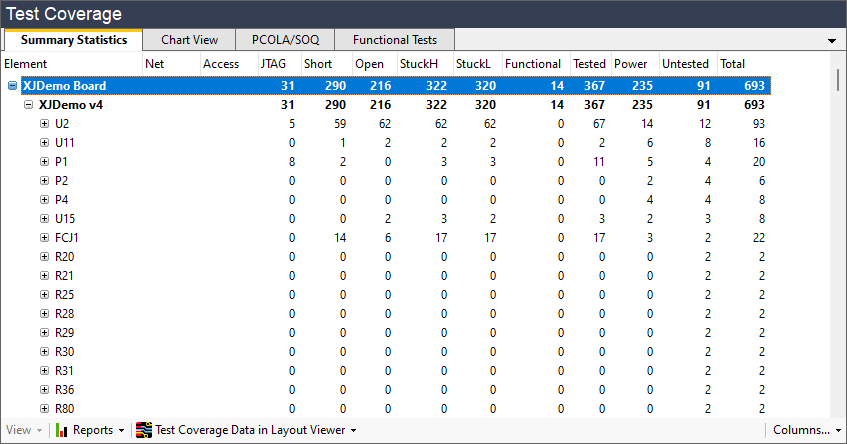
The device at the top of this list, with 12 untested pins, is the JTAG enabled microcontroller U2. With one exception, these untested pins are all Linkage pins - pins which are on a JTAG enabled device but which do not have boundary scan functionality.
It is not uncommon for a JTAG enabled device to have linkage pins and there is nothing that can be done to add boundary scan functionality to these pins. Normally, linkage pins will be used for functions that are incompatible with boundary scan testing for some reason. In this case the untested pins are analog inputs to the processor.
It is sometimes possible to add some coverage for linkage pins by exercising an aspect of the functionality of the JTAG device. In this case the on-chip-debug functionality of the microcontroller can be accessed through the JTAG port to read some analog voltages on these pins; this is done in the XJDemo v4 with XJDirect example project which is installed with XJTAG.
For this exercise you are going to look at the next device down in the list, U11, which has 8 pins untested. These are again analog inputs, but this time they are inputs to an I2C ADC. If you look at the schematic for the circuit around this device you will see that four of the channels are connected to analog sources that can be checked or controlled.
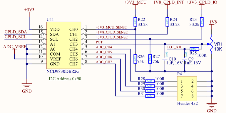
The Tested For section of the Test Device File for the ADC, NCD9830.xje, does not say that these pins are tested because this testing is very specific to this board design. The NCD9830.xje file is generic to any board and as such its test coverage should be declared to only reflect the coverage that can be achieved on any board.
Board-specific testing is added by writing tests in Circuit Code Files. An example of using circuit level tests is shown in the Using Circuit Code Files tutorial exercise.
For the purposes of this exercise you will now assume that a circuit level test has been added for the four analog inputs to U11. In order to tell XJDeveloper about this testing you need to add a Functional Test.
- Click on the Functional Tests tab of the Test Coverage screen.
- Click on
 Add... at the bottom of the Functional Tests tab.
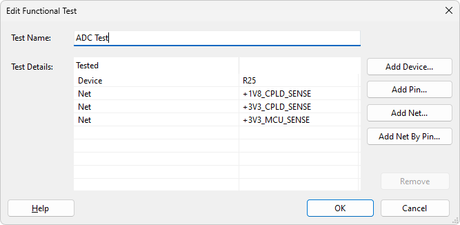
 - Set the Test Name to ADC Test.
- Click on the Add Net... button.
- In the Select Net dialog enter SENSE into the filter text box.
- In the Net Selector expand the All Nets list.
- If the three nets in the list are not selected, hold down the Ctrl key then click with the mouse to select the nets +1V8_CPLD_SENSE, +3V3_CPLD_SENSE and +3V3_MCU_SENSE.
- Click the OK button.
This will add coverage for channels 0, 1 and 2. Channel 3, the POT net, cannot be added in the same way as there are two nets that will be tested by checking this channel is working. In this case you will add device R25 to this functional test. This will add coverage to both of the nets to which this device is connected.
- Click on the Add Device... button.
- In the Select Device dialog enter R25 into the filter text box.
- In the Device Selector select R25 from the All Components list.
- Click on the OK button.
- Click on the OK button in the New Functional Test dialog.
Now go back to the Summary Statistics tab and review the untested pins on U11. The number of Untested pins has now gone down from 8 to 4. However the effect of this Functional test goes beyond U11.
- Click on the Chart View tab on the Test Coverage screen.
A look at the tested pins coverage of the board, shown below, shows that the test coverage for the ADC Test is 16 pins. This includes the four pins on U11 plus the other pins on the nets connected to the four analog inputs. The overall effect of this functional test is to reduce the number of untested pins on the board to 75 pins (10.8%).
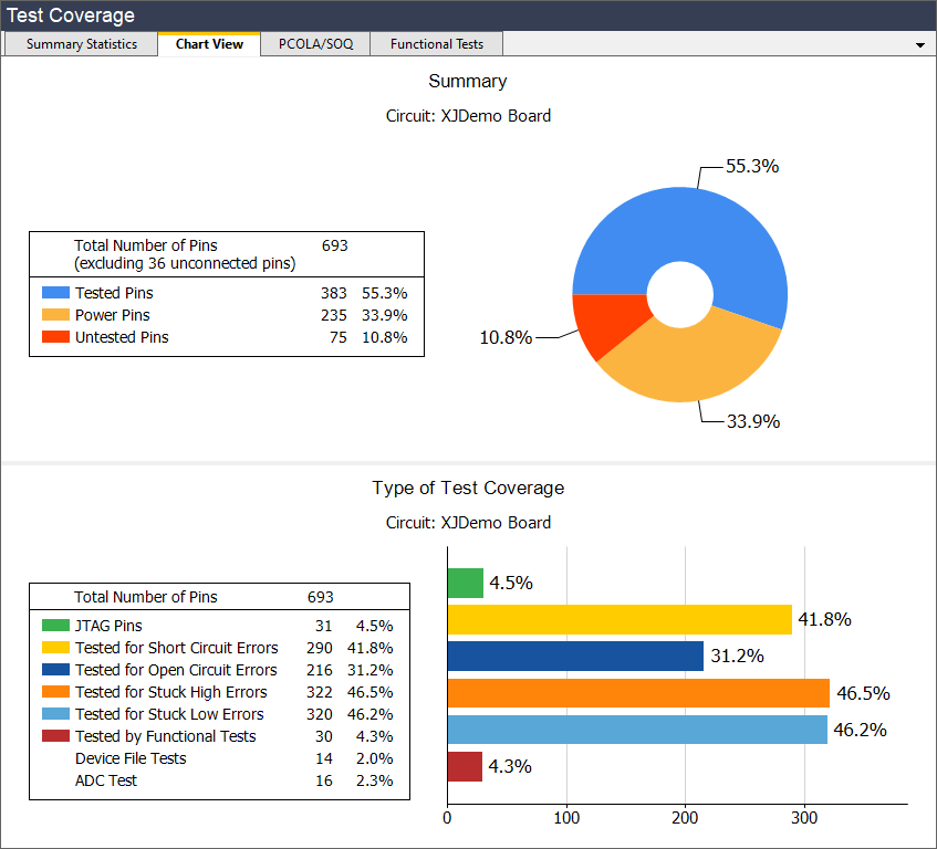
Note that the Chart View tab on the shows results based on the selection in the Summary Statistics tab. If you want to show the whole circuit, or a particular board or device, make sure that is selected before you go to the Chart View.
There are additional functional tests that can be added to this project to reduce the number of untested pins to just 41; this can be seen in the full example version of the project that is installed in the XJTAG shared folders.
Many of the these 40 untested pins come from the linkage pins on the microprocessor and the four untested inputs to the ADC. As with the functional test you have created, these analog inputs do not just affect the pins on the microprocessor and the ADC. Any test will also check the pins on the resistors, capacitors, connectors, etc. on the nets connected to these inputs.
In order to get test coverage for the four untested channels on U11 you would have to use some other mechanism to simulate these analog inputs so they can be checked using the ADC. The XJIO board example provides one mechanism for extending the tests for the XJDemo board to achieve 100% test coverage.
See Also
XJTAG v4.3.0