Creating your XJTAG Project
An XJTAG project contains the description of the circuit you want to test. It references the netlist, schematic and BOM for each board, the BSDL files for the JTAG enabled devices, and other files that describe how devices that do not have JTAG capability are to be treated.
The first step in creating a new project is to create a new folder (the project folder) which will contain all these files. This folder can be located anywhere, so the XJTAG project can be stored in a place that fits with your company's file-naming conventions or into larger project structures, or perhaps somewhere close to the location of design files.
During the tutorial you are going to need the files mentioned above for the XJDemo board. These are contained in a zip file, tutorial4.zip, which was installed as part of XJTAG and can be found in .
XJDeveloper will accept more than 80 ASCII netlist formats – some common examples are Cadence Allegro, PADS PCB, Protel and RINF. For the tutorial we will use ODB++ format as this contains not only netlist information but also layout information. This will be used in the XJTAG layout viewer to display circuit elements and fault conditions that are diagnosed when running tests.
- Extract the zip file tutorial4.zip to a new, empty directory of your choice.
We will now use XJDeveloper to create a test project for the XJDemo v4 board.
XJDeveloper is XJTAG's fully-featured development environment. Full help about using the features in XJDeveloper can be found here or by pressing F1 in XJDeveloper at any time.
- Open XJDeveloper 4.3 from the XJTAG 4.3 folder on your Start Menu.
- Click
 New Project on the start screen, or select New Project from the File menu.
 - Navigate into the folder you have created for your project and enter the Board Test folder.
- Type XJDemo Board as the filename for your project.
- Click on the Save button to begin your project. This will create the following four files in the Board Test folder:
- XJDemo Board.xjd – contains general project information such as notes and comments.
- XJDemo Board.xje – contains all of the information you enter about the circuit you want to test.
- XJDemo Board.settings – used by XJDeveloper to remember project settings.
- Globals.xje – contains global variable and function definitions.
N.B. When you create a new project, the Name of the circuit under test is set to the same value as your XJDeveloper project. This is shown under Circuit Description at the top of the  Boards screen.
After creating the project files, XJDeveloper shows the Boards Screen. Click the Add New Board... tile in the main area of the Boards screen, or the  Add New... button in the tool strip to begin importing a netlist, schematic and BOM:
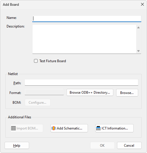
- At the top of the dialog set the board's Name to be XJDemo v4.
Board names are only really significant when you have more than one board in your project and need a way to uniquely identify components.
Adding the netlist, schematic and BOM
Netlist
A netlist is a file output by CAD tools. It describes the components that are on the board and how those components are connected. The netlist for the XJDemo board (in ODB++ format) is contained in the file XJDemo v4_2_ODB.zip which you have already extracted to your project folder.
The ODB++ format can also contain BOM information. However, for reasons set out in the User Guide, we recommend using a separate BOM file when one is available.
- Click Browse....
- Go up one directory level (back to the project folder which you originally created).
- Navigate into the Board Data folder.
- Select XJDemo v4_2_ODB.zip in the Board Data folder, and click Open.
- Click Ignore and continue when asked if you want to import the BOM data XJDeveloper has found in the netlist.
Schematic
XJDeveloper can highlight items in your circuit schematic. To use this feature, schematic files must be in a text-searchable PDF format.
N.B. XJDeveloper will start in the directory where the netlist is located when looking for possible schematic files.
- Click
 Add Schematic....
 - Select XJDemo v4_2.pdf from the Board Data folder and click Open.
- Click No when asked if you want to import the BOM data XJDeveloper has found in the schematic.
The schematic should now be in the list of Schematic PDF Files in the Assign Schematic Files dialog.
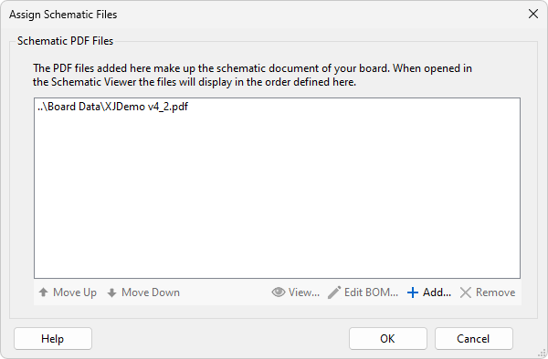
- Click OK to add the schematic to the board.
N.B. The project you create during this tutorial only contains a single board, but it is possible to create a multi-board project. For this reason the word 'circuit' is used to represent the entire unit under test, and can be composed of one or more 'boards'. For an example of a multi-board setup, see the example found in the Help for the XJIO board.
BOM data
BOM data provides extra information about the components on a board. Although it is not strictly necessary for creating a test system with XJDeveloper, the BOM information can be very useful. It allows XJDeveloper to automatically suggest models from its installed libraries that can be used when categorising the non-JTAG devices in the circuit.
Some schematics and netlist formats, such as the ODB++ netlist for the XJDemo board, have BOM information embedded within them. However, when a separate, dedicated BOM file is available it is usually preferable to use that, as it is more likely to reflect the latest PCB build state – particularly information about which devices are fitted to the specific build of the board you are testing.
For this tutorial project, you will import BOM information from a dedicated file.
- Click
 Import BOM... on the Add Board dialog.
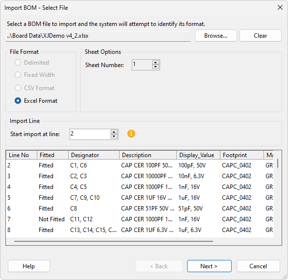
 - Select XJDemo v4_2.xlsx from the Board Data folder and click Open. The Import BOM dialog will now be displayed and the file will be correctly identified as being in Excel format.
- Click Next >.
In the next step of the BOM import you can configure how XJDeveloper will display and use the different data values within the BOM. Columns of data may be assigned to particular BOM fields by first selecting the column then selecting the assignment from the Selected Column Data Type dropdown menu. XJDeveloper will automatically make these assignments if suitable matching text is found in the available column headers.
- Select the first column of data (containing the values Fitted and Not Fitted).
- From the Selected Column Data Type dropdown menu select Unfitted to assign this data type to the selected column.
- Review the assignments made for the other columns (the assignment is shown in parentheses in the column header text).
- Click Next > to preview the data that will be imported.
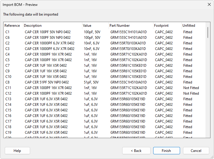
- Click Finish to complete the BOM import process.
- Click OK on the Add Board dialog to add the board to the project.
Unfitted Device Suggestions
XJDeveloper can be configured to identify unfitted devices in several ways. Many BOM files will omit parts which are unfitted, meaning that the absence of an entry in the BOM can be used to identify an unfitted part, but they may also be identified by data in a specific column. You will now check to make sure that the correct options are configured for this project.
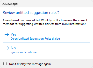
- A prompt will appear asking if you want to review methods for suggesting Unfitted devices; click Yes. If this window does not appear, click
 Unfitted Rules... in the toolbar at the bottom of the Boards screen.
 - Make sure BOM File is selected under Include any devices missing from selected BOM sources.
- Make sure Any other BOM field is not selected.
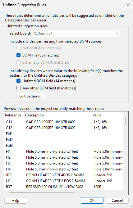
You will see that items such as Fid1 are listed because they are not in the BOM. However, other items such as R37 are listed because the data in the Unfitted column of the BOM for that device matches a regular expression.
- Click OK to confirm the selected options.
- Click
 Save on the main XJDeveloper toolbar to save your project.
The regular expression used to match the data in the Unfitted column can be edited in the Options dialog, which can be accessed by clicking Edit patterns.... This is covered in more detail in the User Guide, along with more information about getting the most out of the BOM data.
The next stage
Having given XJDeveloper the raw information about the circuit to be tested, you can now start categorising devices and nets.
XJDeveloper needs to know the devices with JTAG capability because these are the devices that it directly controls during testing. You will also need to give XJDeveloper more information about the devices that are connected to these JTAG devices so they can also be tested. But before this, you first need to give XJDeveloper a list of the power nets and ground nets.
XJTAG v4.3.0