Automatically Finding the JTAG Chain
XJDeveloper can use the netlist and BSDL files to try to find the JTAG chains automatically:
- XJDeveloper compares the contents of the BSDL files to information from the netlist to try to identify the circuit's JTAG devices. It identifies candidates by looking for devices with suitable reference designators (e.g. U2, IC5) and approximately the right number of pins, and checks the pins that the BSDL file says are JTAG signals are connected to nets with likely-looking names.
- Having identified potential JTAG devices, XJDeveloper attempts to find a signal path that puts them into chains that start and end at a connector.
- Potential signal paths include those that pass through two-pin devices such as low-value resistors and links.
This attempt to automatically find the JTAG chains is successful for most simple chains (i.e. ones where the JTAG ICs are the only devices in the chain with more than two pins). If XJDeveloper cannot form a complete chain, the software will identify as much of it as possible, leaving you just to complete the remaining parts. This can occur if, for example, the chain includes buffers or resistor packs because XJTAG does not know at this stage how signals are routed through such devices.
- It is important to have already categorised the power and ground nets before automatically detecting the JTAG chains because the JTAG signal nets will have pull-resistors on them. If the power and ground nets have not been categorised, XJDeveloper may attempt to route the chain through those pull-resistors and via power nets.
- The chain identification algorithm searches for a connector that could be providing the circuit's JTAG interface, and it expects to find the TDI and TDO signals coming to the same connector. If the JTAG interface is provided via test points, XJDeveloper will be unable to complete the chain because it will consider TDI and TDO to be on separate connectors. However, it is normally still worth using the automatic detection to provide the rest of the chain. The remaining parts can then be completed manually.
- This process will attempt to find all the chains in the circuit. If your design contains multiple chains but you just want to do an automatic definition for one of them, you should start by manually defining the circuit's TDI connection for the chain of interest and then performing an automated definition for that chain – see Entering a Chain's Name and its Start and End Points.
When using the automatic method of finding the JTAG chains, it is normally best to follow this process:
- Unless you already know the circuit very well, it is best to start by using the Schematic Viewer to note the number of JTAG chains, the number of JTAG devices in each chain, and the connector pins being used. This will allow you to confirm that XJDeveloper's suggestions for the JTAG chains are correct.
- Use the Suggest Chains... button to attempt to identify the chain(s) automatically. The BSDL files must be provided at this point.
- If necessary, manually complete the chain.
- When using the Schematic Viewer to search for JTAG devices, it is best to use a text search for TMS (designs tend to name the other JTAG signals in non-standard ways whereas TMS is normally used unchanged throughout). Use a text search instead of a net search so that net names that include TMS (such as MCU_TMS) will be found as well as labels on device symbols.
To perform an automatic search for the JTAG chain(s), click Suggest Chains... in the Chain Setup section:
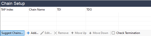
Figure 5: Running a Circuit Analysis to Automatically Identify the JTAG Chain
Providing the BSDL Files
Having clicked Suggest Chains..., you will be presented with a dialog box in which to provide the location of the BSDL files:
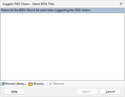
Figure 6: Selecting BSDL Files for an Automatic JTAG Chain Search
If you are using the library (and links to the latest files have already been added), use Browse Library... to locate the BSDL files. Repeat until all the required BSDL files are listed in the dialog box. Each time a file is selected, you will be asked if you want to add a copy of the BSDL file from the library into your project. It is recommended that this is always done, to remove the risk of your project being affected by someone else updating or editing the file referenced in the library.
- If you are working with an old circuit, the IC vendors may have updated their silicon after your board was built. In that situation, the latest available BSDL file may not work with the older version of device on your board.
If you are not using the library, click Browse... instead. Navigate to the location of the files and select all the relevant BSDL files. If they are stored in several locations, click Browse... again to select any remaining files. You will be offered the opportunity to save the BSDL files into the BSDL Library, but this should not be done if the BSDL file is stored in your project folder (see Collecting the Required BSDL Files above).
Once all the required BSDL files are listed in the dialog box, click Next >.
Accepting XJDeveloper's Chain Proposal
Now the BSDL files have been provided, XJDeveloper can attempt to find the circuit's JTAG chains. A dialog box will then open to show what was found. If it could not complete a chain, it will display as much of the signal path as it was able to identify.
A dialog box similar to the one below will be opened:
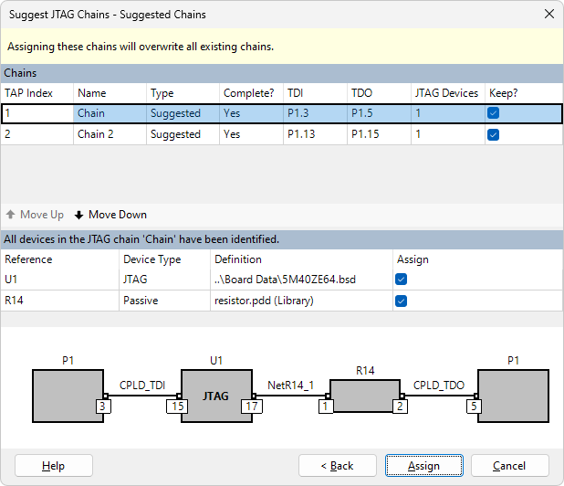
Figure 7: XJDeveloper's Suggestion of a Circuit's JTAG Chains
The dialog box has three sections:
- The upper section lists the chains that were found, with each one presented on its own row. If a complete chain was found starting and ending at a connector, Yes will be present in the Complete? column. The number of JTAG devices found in the chain is also displayed in the row.
- The middle section displays the devices in the chain that is selected in the upper section. This includes the JTAG device(s) and any 2-pin devices found in the chain.
- The bottom section shows the selected chain in a graphical form, together with pin numbers, net names, and the reference designator of each device in the chain.
Select a different chain in the upper section to change the displayed information.
The middle section is used to categorise the devices that were found in the chain. In the above example, U1 is being suggested as a JTAG device, and R14 as a passive series connection. If any of these suggestions are incorrect, remove its tick from the Assign column.
The information in all three sections should be checked to confirm it is correct.
- If a device in the chain has already been categorised, it will still be listed in the middle section but its Assign checkbox will be greyed-out.
If the JTAG chain goes through a resistor pack or a buffer, XJDeveloper will be unable to complete the chain because it does not know the pin on which the signal leaves the device. In that case, it will be necessary to complete the chain manually.
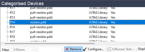
- If a passive device has been incorrectly categorised, its categorisation can be removed on XJDeveloper's Categorise Devices screen by removing the device from the list of categorised devices: select the device in the Categorised Devices section and click Remove:
- The categorisation of a JTAG device can be removed in the JTAG Devices section of the JTAG Chain screen by selecting the device and clicking that section's Remove button.
- If you need to remove a complete chain, remove the categorisation of its non-JTAG devices on the Categorise Devices screen, and remove that chain's JTAG devices' categorisations on the JTAG Chain screen (see the 2 tips above). Then, remove the assignments of TDI and TDO pins by selecting the chain in the top section of the JTAG Chain screen and clicking that section's Remove button.
Additional guidance on correcting mistakes is provided later.
If the circuit has more than one chain, it is strongly recommended that their names be changed from the default of Chain, Chain 2, Chain 3, etc.: double-click in the Chain Name column and enter a name that is more relevant to your circuit (e.g. MCU Chain). This will help when you come to assign the XJLink2's pins to the different JTAG signals later in the project setup.
If a proposed chain is totally wrong or you don't want to add that chain to the project, make sure the checkbox in the Keep? column next to the chain is unchecked. You can then enter the details manually.
If a proposed chain is partially correct, it is often easiest to accept the proposal and edit the chain afterwards on the JTAG Chain screen.
Once you are happy to accept the information in the dialog box, click Assign. This will categorise the appropriate devices and return you to the JTAG Chain screen. Note that this categorises the devices in all the proposed chains, not just the displayed chain. To check all the categorisations that will be performed, select the different chains one-by-one in the upper section first.
If the device contains multiple cores that support JTAG or it uses non-standard boundary cells that are not supported by files in the XJTAG library, the chain will need subsequent editing to provide this additional information. This can be done after the chain has been defined as described in Adding a Multi-Core JTAG Device and Loading a Package File below.
Allocating the Order of Multiple Chains (TAP Index)
If a circuit has multiple chains, it is important to note the TAP Index that is assigned to each chain because the index is used to associate the different TDI / TDO pairs with individual physical pins on the XJLink2. The indexes assigned to the chains are listed in the TAP Index column as shown in Figure 8 below. The TDI / TDO pairs used by each TAP Index are as follows:
- First chain (TAP Index 1) uses TDI and TDO.
- Second chain (TAP Index 2) uses TDI2 and TDO2.
- Third chain (TAP Index 3) uses TDI3 and TDO3.
- Fourth chain (TAP Index 4) uses TDI4 and TDO4.
When you come to map the XJLink2's pins to the circuit's JTAG signals, you must pay attention to the JTAG signal names listed above to ensure that each group of the XJLink2's JTAG signals is connected to the correct chain in the circuit.
In the example of Figure 8 below, XJDeveloper will assume TDI on the XJLink2 has been connected to pin 3 of connector P1, and that TDI2 has been connected to pin 13.
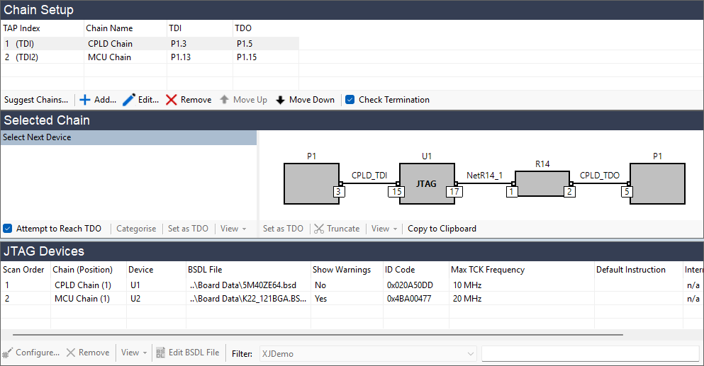
Figure 8: The TAP Index assigns chains to the XJLink2's TDI and TDO Pins
If you have already defined the XJLink2 pin-out, you can use the Move Up and Move Down arrows in the Chain Setup section to change the index assigned to each chain (Figure 8). Their order should be adjusted so that the JTAG chains match those allocated to the XJLink2's pins.
XJTAG v4.3.0